GOVERNORS
Speed Limits & Repair
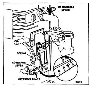
Adjustment
With crankcase cover, carburetor and all linkage
installed, loosen screw holding governor lever to
governor shaft. Place throttle in high speed position.
Hold throttle in this position and with a screwdriver turn
governor shaft COUNTERCLOCKWISE as far as it will
go. Tighten screw holding governor lever to governor
shaft to 35-45 in. lbs. torque (.4-.52 mkp, 4.0-5.0 N•m).
See fig. 9. Before starting engine, manually move
governor linkage to check for any binding. Correct any
binding in linkage or carburetor.
Fig. 9. Governor Adjustment
MECHANICAL GOVERNOR
CAST IRON MODELS
9, 14, 19, 190000, 200000, 23, 230000, 240000, 300000,
320000
Disassembly
To service, remove engine base. Remove the cotter key
and washer from outside end of governor shaft. Remove
governor crank from inside the crankcase. Governor
gear slides off the shaft.
Re-Assembly
Assemble the governor gear and cup assembly on shaft
protruding on inside of cylinder. Then insert governor
shaft assembly through bushing from inside of cylinder.
Assemble governor lever to governor shaft loosely.
NOTE: Later models have a spacer between governor
shaft assembly and bushing.
Adjustment
Loosen screw holding governor lever to governor shaft.
Place throttle in high speed position. Hold throttle in this
position and with a screwdriver turn governor shaft
COUNTERCLOCKWISE as far as it will go. Tighten
screw holding governor lever to governor shaft to 35-45
in. lbs. torque (.4-.52 mkp, 4.0-5.0 N•m). See Fig. 9.
Before starting engine, manually move governor linkage
to check for any binding.
NOTE: If governor bushing is replaced it should be finish
reamed to .239-.2385 (6.07-6.05 mm) after installation
using Stanisol or kerosene as lubricant.
MECHANICAL GOVERNOR
ALUMINUM MODELS 94000
The mechanical governor used on Model Series 94000 is
illustrated in Fig. 10. The governor gear is part of the oil
slinger.
Fig. 10. 94000 Governor
Disassembly
Before governor can be serviced, it is necessary to
remove engine sump. To remove governor shaft,
remove lever adjusting screw, Fig. 10 and loosen lever
clamp screw, Fig. 10. Slide off clamp. Lift governor
lever up to release slot in governor shaft and slide
governor shaft out of bushing. If oil slinger and governor
gear assembly interferes, remove.
4