TM 5-4240-5501-148P
ALTERNATOR
11/2 Amp
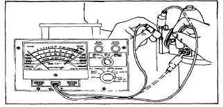
Fig. 158 - Testing Rectifier
Fig. 159 - Testing Rectifier (Alternate Style)
Replacing Rectifier
Cut stator wires close to rectifier so that stator wires
remain as long as possible. Discard old rectifier. Strip
insulation back 3/8" from stator wires. Replacement
rectifier has two exposed wires which are already
stripped of insulation. Twist and solder each stator wire
to a rectifier wire. Insulate each connection with
electrical friction tape, keeping connected areas as
compact as possible. Remove and discard original
ground wire from drive housing. Fasten new ground wire
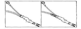
to drive housing. Locate wires as shown in Figure 160.
Retest rectifier as shown in Figure 158 or 159.
Fig. 160 - Replacing Rectifier
Replacing Defective Rectifier Box
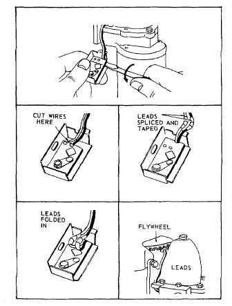
Remove rectifier box from starter motor. Use a
screwdriver to pry under the fiber board as shown in
Figure 161. Fiber will break, exposing soldered
connections between rectifier and stator leads. Cut
stator leads close to eyelets so stator leads remain as
long as possible. Strip insulation back to expose about
3/8" of wire. Discard defective rectifier box.
Fig. 161 - Replacing Rectifier
Replacement rectifier box has short leads, the tips of
which are already stripped of insulation. Twist and solder
each stator lead to a rectifier lead. Insulate each
connection with electrical friction tape, keeping splices as
compact as possible because of small space available.
Form splices into bottom of rectifier box as shown in
Figure 161. and re-assemble rectifier box to starter
motor. Pull gently on leads to insure a firm connection
and locate them as shown in Figure 161. so they cannot
rub on flywheel ring gear. Recheck output as shown in
Figure 153.
50