TM 5-4240-501-14P
IGNITION
FLYWHEEL TYPE—INTERNAL BREAKER
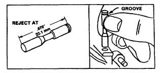
Breaker Point Plunger
If the breaker point plunger is worn to a length of .870"
(22.1 mm) or less, it should be replaced. Plungers must
be inserted with groove at the top when installed or oil
will enter breaker box. See Fig. 17.
Checking Plunger
Inserting Plunger
Fig. 17
Install Breaker Points
Insert breaker plunger into the plunger hole in cylinder.
Breaker points as shown in Fig. 14 are installed by
placing the mounting post of the breaker arm into the
recess in the cylinder so that the groove in the post fits
the notch in the recess. Tighten the mounting screw
securely. Use a 1/4" spinner wrench if available. Slip
the open loop of breaker arm spring through the two
holes in the arm, then hook closed loop of spring over
the small post protruding from the cylinder. Push flat end
of the breaker arm into the groove in the mounting post.
This places tension on the spring and pulls arms against
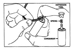
the plunger. If condenser post is threaded, attach the
coil primary wire (and ground wire if furnished) with the
lockwasher and nut. If primary wire is fastened to
condenser with spring fastener, compress spring. Fig.
18, and slip primary wire (and ground wire where
furnished) into hole in condenser post. Release spring.
Lay the condenser in place and tighten the condenser
clamp securely.
Fig. 18 - Assembling Condenser and Ignition Wires
When installing breaker point assemblies, as shown in
Fig. 13, be sure the small boss on the magneto plate
enters the hole in the point bracket. Mount points to
magneto plate or cylinder with lock screw. Fasten the
armature lead wire to the breaker points with the clip and
screw. If these lead wires do not have terminals, the
bare end of the wires can be inserted into the clip and
screw tightened to make a good connection. Do not let
the ends of the wire touch the point bracket or magneto
plate or ignition will be grounded.
Adjusting Breaker Point Gap
Turn crankshaft until points open to widest gap. When
adjusting breaker point assemblies as shown in Fig. 19,
move condenser forward or backward with screw driver
until a gap of .020" (0.5 mm) is obtained. Breaker points
assemblies as shown in Fig. 20, are adjusted by
loosening lock screw and moving contact point bracket
up or down. Gap is .020" (0.5 mm).
Fig. 19 - Adjusting Breaker Point Gap
Fig. 20 - Adjusting Breaker Point Gap
2
6