TM 9-2350-238-34-1
2 - 3 1 . M A I N T E N A N C E O F F A B R I C F U E L C E L L I N S T A L L A T I O N A N D F A B R I C F U E L C E L L
F I L L E R B L O C K S ( C O N T ) .
I N S T A L L A T I O N ( C O N T )
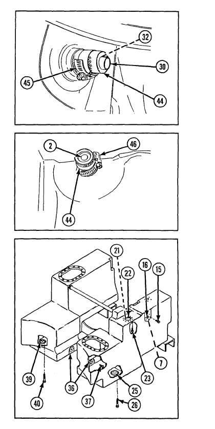
3 8 F r o m i n s i d e r i g h t f a b r i c f u e l c e l l , p u sh
crossover vent tube (30) toward left fabric
fuel cell. Work fabric fuel cell nipples (44)
over hull vent flange (32) until crossover
vent tube is evenly spaced in both right
and left fabric fuel cells. Secure crossover
vent tube (30) to right and left nipples with
h o s e c l a m p s ( 4 5 ),
3 9 U n d e r l e f t f a b r i c f u e l c e l l a c c e s s o p e n i n g,
work left fabric fuel cell over fuel return
a d a p t e r ( 2 ) . E x t e n d f u e l r e t u r n a d a p t er
through right fabric fuel cell nipple (44).
Secure right fabric fuel cell nipple with
h o s e c l a m p ( 4 6 ).
4 0 T o r q u e t h e f o l l o w i n g c a p s c r e w s t o 1 0 8 . 0
to 120.0 in.-lb (12.2 to 13.6 N-m):
a .
b .
c.
d .
e .
six capscrews (15) securing right fabric
fuel cell (7) to coolant heater fuel intake
( 1 6 ).
ten capscrews (23) securing nut ring
(21) to underside of hull at fuel filler
neck and strainer element access (22).
Fill top of ten capscrew holes with
s e a l i n g c o m p o u n d .
six capscrews (26) securing right fuel
drain nut ring (25) to hull.
eight capscrews (37) securing right and
left fabric fuel cell interconnects (36).
six capscrews (40) securing left fuel
drain nut ring (39) to hull.
2 - 62