SECTION V: CONTROLS AND LINKAGES
TM 9-2350-256-20
2
Inspect core tips for nicks and distortion.
3
Inspect all threaded parts for cross threading and nicks.
4
Inspect clamps, bracket, and welded pad and plate for cracks, distortion, and breakage. Replace all damaged parts.
If welded pad and plate are damaged, notify Direct Support.
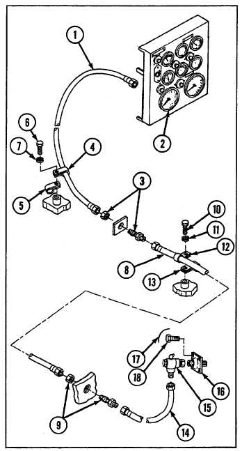
d. INSTALLATION
1
Install bracket (25) with four screws (29) and four new lockwashers (30). Secure four screws with new lockwire (28).
2
Install adapter assembly (21) on bracket (25) with two screws (26) and two new lockwashers (27).
3
Install flexible shaft (19) on adapter assembly (21) and
secure with three clamps (24), three new lockwashers
(23), and three screws (22).
4
Install adapter (16) with four screws (18). Secure four
screws with new lockwire (17).
5
Install adapter (9) and elbow (15).
6
Connect flexible shaft (14) to adapter (9) and elbow
(15).
7
Install adapter (3).
8
Install flexible shaft (8) on adapters (3 and 9) and
secure with clamps (12 and 13) held by screw (10) and
new lockwasher (11).
9
Connect flexible shaft (1) on adapter (3).
10 Install flexible shaft (1) with two clamps (4 and 5),
screw (6), and new lockwasher (7).
11 Connect flexible shaft (1) to tachometer (2).
12 Connect flexible shaft (19) to speedometer (20).
9-145