SECTION V: CONTROLS AND LINKAGES
TM 9-2350-256-20
9
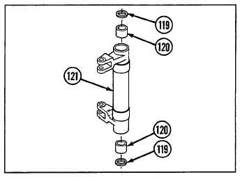
Remove two seals (119) and two bearings (120) from
each of two bell cranks (121).
c.
ASSEMBLY
1
Install two new seals (119) and two new bearings
(120) to each of two bell cranks (121).
2
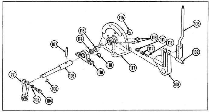
If removed, install two lubrication fittings (116) to
base (117) and fitting (118) to bearing unit (110).
3
Install two bearings (115) and new seal (114).
4
Install plunger (113), spring (112), and setscrew
(111).
5
Install bearing unit (110), segment assembly (109), shaft (108), and straight pin (107).
6
Install key (106), lever (22), new lockwasher (105), and screw (104).
7
Install lever (103) and straight pin (102).
8
Install mounting bracket (101), three spacers (100), three new lockwashers (99), three bolts (98), and knob
(97).
9
Install lever (96), two straight pins (95), and new cotter pin (94).
d.
INSTALLATION
1
Install mounting bracket (78) with flat washer (93), three new lockwashers (92), and three screws (91).
9-165