CHAPTER 9: MAINTENANCE OF HULL- AND CAB-RELATED COMPONENTS
TM 9-2350-256-20
9-80 REPLACE/REPAIR/SERVICE SERVICE BRAKE CONTROLS AND LINKAGES-Continued
13
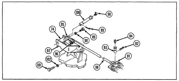
Install bracket assembly (97) and lever (74) with grooved pin (100), new cotter pin (99), lubrication fitting (98), four
new lockwashers (102), and four screws (101).
14
Install rod end (95) and nut (96) to rod assembly (88).
15
Connect rod assembly (88) to plate assembly (91) with grooved pin (93), new cotter pin (92), and lubrication fitting
(94).
16
Install rod assembly (88) to lever (74) with screw (89) and new lockwasher (90).
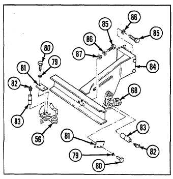
17
If removed, install bracket assembly (84) with six
screws (85), six new lockwashers (86), and three flat
washers (87).
NOTE
Install accelerator controls and linkages if
removed (see paragraph 9-78).
18
Install levers (56 and 68) each with pin retainer (81),
grooved pin (83), lubrication fitting (82), two screws
(80), and two new lockwashers (79).
9-192