APPENDIX H: USAREUR SAFETY LIGHTING MODIFICATION KIT
TM 9-2350-256-20
H-4
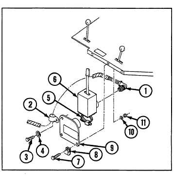
DIRECTIONAL SIGNAL CONTROL AND MOUNT ASSEMB LY
THIS TASK COVERS
a. Removal
b. Installation _
INITIAL SET-UP
Tools:
Parts:
Tool kit, general mechanic's (Appendix C, item 53)
Lockwashers (3) (Appendix G, item 130)
WARNING
Be certain MASTER switch is OFF when working on electrical system to avoid electrical shock and burns.
a.
REMOVAL
1
Disconnect and remove wiring harness (1), clamp
(2),
screw (3), and lockwasher (4).
2
Loosen clamp (5) and remove directional signal
control (6).
3 Remove two screws (7), clamp (8), mount assembly
(9), two lockwashers (10), and two nuts (11).
b.
INSTALLATION
1
Install mount assembly (9), clamp (8), two screws
(7), two new lockwashers (10), and two nuts (11).
2
Connect directional signal control (6) to mount
assembly (9) and tighten clamp (5).
3
Install clamp (2), new lockwasher (4), and screw (3).
Install wiring harness (1) and connect to directional
signal control (6).
H-5
MIRROR AND MOUNT ASSEMBLIES
THIS TASK COVERS
a. Removal b. Installation
INITIAL SET-UP
Tools:
Parts:
Tool kit, general mechanic's (Appendix C, item 53)
Lockwashers (10) (Appendix G, item 131)
NOTE
The following procedures apply to both left and right mirror assemblies.
a.
REMOVAL
1
Remove screw (1), lockwasher (2), nut (3), and mirror (4) from mount assembly (5).
2
Remove four screws (6), four lockwashers (7), four nuts (8), and mount assembly (5).
H-6