SECTION V: TROUBLESHOOTING
TM 9-2350-256-20
WARNING
Remove all jewelry such as rings, dog tags,
bracelets, etc. If jewelry contacts a metal surface
a direct short may result in instant heating of
tools, damage to equipment, and injury or death
to personnel.
C
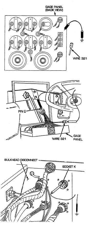
Reconnect wire 27E to transmission oil pressure gage.
Disconnect wire 321 from transmission oil pressure
gage.
Turn
MASTER
switch
on
and
check
transmission
oil
pressure
gauge
for
operation.
Transmission oil pressure gage should read full scale.
Ground case of transmission oil pressure gage and
check gage for operation. Gage should read "O."
Turn MASTER switch OFF. If transmission oil
pressure gage reads correctly, go to step D. If
transmission oil pressure gage fails to read correctly,
replace transmission oil pressure gage (see paragraph
6-8).
D
Disconnect gage panel to bulkhead wiring harness
from gage panel. Check wire 321 in gage panel
harness for continuity by placing red lead of
multimeter on wire 321 and black lead on pin C. If
continuity is present, go to step E. If continuity is not
present, repair/replace wire 321 of gage panel wiring
harness (see paragraph 6-44).
E
Reconnect wire 321 to transmission oil pressure gage
and bulkhead wiring harness to gage panel. Install
ground strap (5), two lockwashers (4), two screws (3),
gage panel (6), three lockwashers (2), and three
screws (1). Open air inlet doors (TM 9-2350-256-10).
Disconnect bulkhead to engine bracket and rear fuel
tank wiring harness from bulkhead disconnect. Place
red lead of multimeter in socket K of wire 321 and
black lead to ground. Turn MASTER switch on and
check for voltage. Turn MASTER switch OFF. If
voltage is present, go to step F. If voltage is not
present, repair/replace wire 321 of gage panel to
bulkhead wiring harness (see paragraph 6-45 for dual
voltage; 6-46 for single voltage).
2-121