SECTION V: Troubleshooting
TM 9-2350-256-20
WARNING
Remove all jewelry such as rings, dog tags,
bracelets, etc. If jewelry contacts a metal
surface a direct short may result in instant
heating of tools, damage to equipment, and
injury or death to personnel.
G
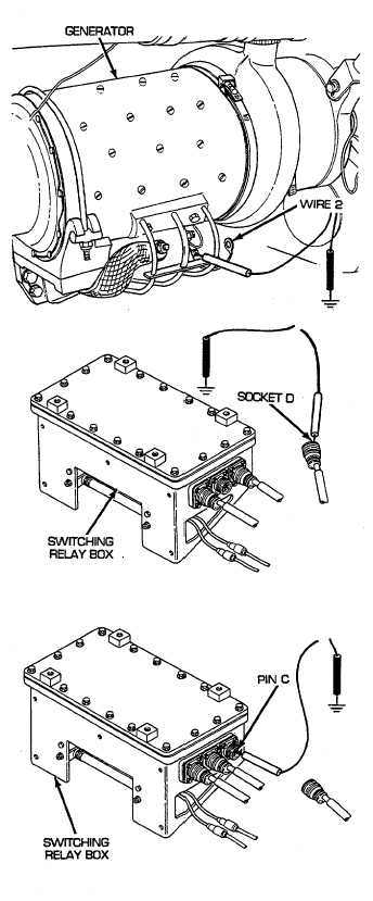
Reconnect generator power lead assembly to engine
disconnect. Remove powerplant (see paragraph 3-1).
Disconnect wire 2 of generator power lead assembly
from generator. Place red lead of multimeter on
terminal of generator and black lead to ground. Turn
MASTER switch on, start engine, open generator
cutout switch and check for voltage. Turn engine and
MASTER switch OFF, and close generator cutout
switch. If voltage is present, repair/replace generator
power lead assembly (see paragraph 6-36). If voltage
is not present, replace engine generator (see
paragraph 6-1).
H
Reconnect bulkhead to engine bracket and rear fuel
tank transmitter wiring harness to switching relay box.
Disconnect APU and engine generator relays to
voltage regulator wiring harness from switching relay
box. Place red lead of multimeter in socket D of wire
1-61 and black lead to ground. Turn MASTER switch
on, start engine, open generator cutout switch and
check for voltage. Turn engine and MASTER switch
OFF and close generator cutout switch. If voltage is
present, go to step I. If voltage is not present,
repair/replace wire 1-61 of APU and engine generator
relays to voltage regulator wiring harness (see
paragraph 6-81).
I
Reconnect APU and engine generator relays to
voltage regulator wiring harness to engine regulator.
Disconnect bulkhead to engine bracket and rear fuel
tank transmitter wiring harness from switching relay
box. Place red lead of multimeter on pin C of wire 1
and black lead to ground. Turn MASTER switch on,
start engine, close generator cutout switch and check
for voltage. Turn engine and MASTER switch OFF
and open generator cutout switch. If voltage is
present, go to step J. If voltage is not present,
replace switching relay box (see paragraph 6-13).
2-133