CHAPTER 2: VEHICLE MAINTENANCE INSTRUCTIONS
TM 9-2350-256-20
2-19 ELECTRICAL TROUBLESHOOTING-Continued
HYDRAULIC RESERVOIR MONITORING SYSTEM GAGE AND TRANSMITTER-Continued
WARNING
Remove all jewelry such as rings, dog tags ,
bracelets, etc. If jewelry contacts a metal
surface a direct short may result in instant
heating of tools, damage to equipment, and
injury or death to personnel.
D Reconnect wire 664A to hydraulic oil temperature
gage. Disconnect wire 664 from hydraulic oil
temperature gage. Place red lead of multimeter on
terminal of hydraulic oil temperature gage and
black lead to ground. Turn MASTER switch on and
check for voltage. Turn MASTER switch OFF. If
voltage is present, go to step E. If voltage is not
present, replace hydraulic oil temperature gage
(see paragraph 6-11).
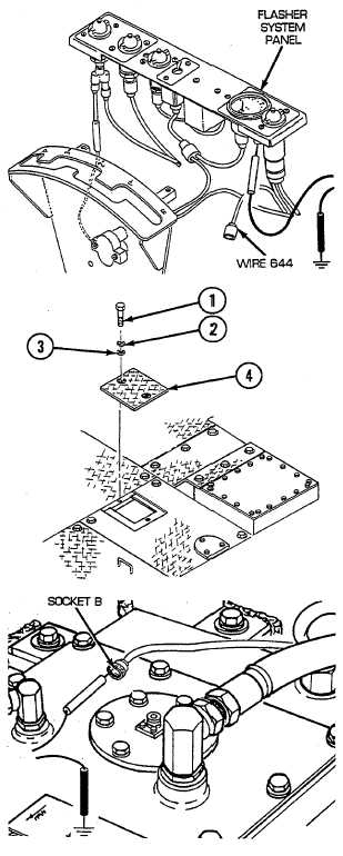
E Reconnect wire 664 to hydraulic oil temperature
gage. Remove two screws (1), two lockwashers (2),
two flat washers (3), and rear intermediate right
access floor plate (4). Disconnect flasher system
panel wiring harness at hydraulic reservoir
disconnect. Place red lead of multimeter in socket B
of wire 664 and black lead to ground. Turn MASTER
switch on and check for voltage. Turn MASTER
switch OFF. If voltage is present, go to step F. If
voltage is not present, repair/replace wire 664 of
flasher system panel wiring harness (see
paragraph 6-48).
2-348