SECTION III: PRINCIPLES OF OPERATION
TM 9-2350-256-20
1-22 MECHANICAL TRANSMISSION AND MAIN HYDRAULIC SYSTEM PUMP
NOTE
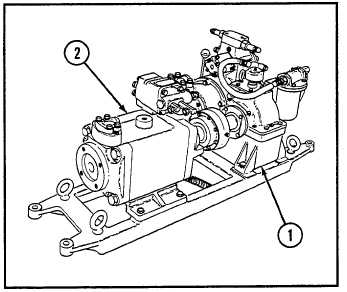
1 Mechanical transmission
2 Main hydraulic system pump
The following callouts are found in Figure 1-14.
The mechanical transmission and hydraulic pump
assembly is mounted in the rear of the hydraulics
compartment, under the crew compartment subfloor
plates. The engine drives the mechanical transmission
(1) through the PTO drive shaft coupled to the PTO
coupling at the accessory end of the engine. The
mechanical transmission drives the main hydraulic
system pump (2). The pump provides hydraulic
system pressure.
Figure 1-14. Mechanical Transmission and
Main Hydraulic System Pump.
1-23 MAIN HYDRAULIC SYSTEM
The main hydraulic system supplies power for the control and operation of the spade, hoisting boom, hoist winch, and
main winch, and for releasing the mechanically applied main and hoist winch brakes. System power is obtained from the
main hydraulic pump driven by the mechanical transmission.
1-24 APU
a. GENERAL
The APU consists of an overhead-valve, two-cylinder, four-cycle, air-cooled, diesel engine connected directly to a 300-A,
28-V, shunt-wound, dc generator (which is also used as a starter), and an auxiliary hydraulic system pump. The APU
provides electrical power to charge the vehicle batteries, and hydraulic power to raise and lower the spade, stow and
raise the boom, and retrieve the main and hoist winch cables.
b. STARTING AND GENERATING SYSTEMS
The 300-A, 28-V generator mentioned above is also used as a starter motor. This is accomplished by first feeding 24 V
dc to the field coil of the generator from the preheat relay when the preheat switch is activated, and then by applying 24
V dc to the generator armature through a starting relay when the start switch is activated. This motorizes the generator,
which is directly coupled to the engine by a drive chain. When the engine starts, the current in the generator armature
reverses direction, and the system automatically changes from a motorizing mode to a generating mode. After the
engine starts, the start and preheat switches must be released to prevent loading down the engine since the voltage
regulator is bypassed during this start cycle, and full voltage is being applied to the field. After the engine has started,
and the preheat and start switches are released, the generator output is controlled by a solid-state voltage regulator and a
current-limiting device.
1-31