CHAPTER 6: MAINTENANCE OF ELECTRICAL SYSTEMS AND CIRCUITS
TM 9-2350-256-20
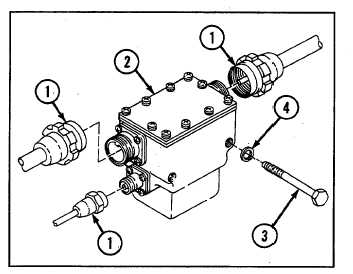
6-7 REPLACE ENGINE AND APU ARMATURE RELAY (SINGLE VOLTAGE)
THIS TASK COVERS
a.
Removal
b. Installation
INITIAL SET-UP
Tools:
Parts:
Equipment Condition:
Tool kit, general mechanic's
Lockwashers (2) (Appendix G,
Air inlet doors removed (see
(Appendix C, item 53)
item 131)
paragraph 9-56)
WARNING
Be certain MASTER switch is OFF when working on electrical system to avoid electrical shock and bums.
a REMOVAL
1
Disconnect three connectors (1).
2
Remove engine generator relay and housing (2) by
removing two screws (3) and two lockwashers (4).
b. INSTALLATION
1
Install engine generator relay and housing (2) using
two screws (3) and two new lockwashers (4).
2 Connect three connectors (1).
NOTE
Follow-on maintenance:
Close air inlet doors
(see paragraph 9-56)
SECTION II: GAGES AND SWITCH PANELS
Para.
Task
Page
6-8
Replace/Repair Gage Panel Assembly ...........................................................................................
6-18
6-9
Replace/Repair Electrical Accessories Panel .................................................................................
6-26
6-10
Replace/Repair Main Switch Panel Assembly.................................................................................
6-31
6-11
Replace/Repair Flasher System Panel and Related Parts ..............................................................
6-36
6-12
Replace Heater Control Box ..................................................... .....................................................
642
6-8 REPLACE/REPAIR GAGE PANEL ASSEMBLY
THIS TASK COVERS
a. Removal
b. Disassembly
c. Assembly
d. Installation
INITIAL SET-UP
Tools:
Parts:
Tool kit, general mechanic's (Appendix C, item 53)
Drivescrews (6) (Appendix G, item 12)
Lockwashers (12) (Appendix G, item 104)
Lockwashers (2) (Appendix G, item 106)
Lockwashers (3) (Appendix G, item 130)
Lockwashers (2) (Appendix G, item 132)
6-18