CHAPTER 6: MAINTENANCE OF ELECTRICAL SYSTEMS AND CIRCUITS
TM 9-2350-256-20
6-8 REPLACE/REPAIR GAGE PANEL ASSEMBLY-Continued
12 Disassemble wiring harness (see Chapter 6, Section VII).
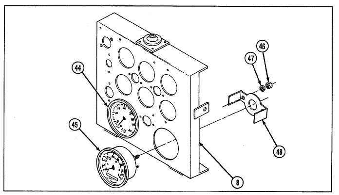
13 Remove speedometer (44) and tachometer (45) by removing two nuts (46), two lockwashers (47), and bracket
(48). Pull speedometer and tachometer from front of gage panel (8).
c. ASSEMBLY
1
Insert speedometer (44) and tachometer (45) through front of gage panel (8). Install speedometer and
tachometer using bracket (48), two nuts (46), and two new lockwashers (47) for each.
2
Assemble wiring harness (see Chapter 6, Section VII).
3
Install fuel selector switch (40) and fuel selector switch instruction plate (41) to gage panel (8) using two
screws (42) and two new lockwashers (43). Connect three connectors (39) to fuel selector switch.
4
Install ID plates (35, 36, and 37) using two new drivescrews (38) for each.
5
Install battery generator indicator meter (24), engine oil temperature gage (27), engine oil pressure gage (28),
fuel tank level gage (29), transmission oil temperature gage (30), and transmission oil pressure gage (31)
through front of gage panel (8).
6
Install six clamps (32) using two new lockwashers (34) and two nuts (33) for each.
6-22