SECTION II: GAGES AND SWITCH PANELS
TM 9-2350-256-20
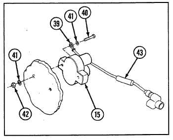
17 Remove circuit breaker (15) and disconnect ground
lead (39) by removing two screws (40), three
lockwashers (41), and two nuts (42). Remove diode
assembly (43).
18 Disassemble wiring harnesses and lead assembly
(see Chapter 6, Section VII).
b. INSTALLATION/ASSEMBLY
1
Install diode assembly (43). Install circuit breaker
(15) and connect ground lead (39) using two screws
(40), three new lockwashers (41), and two nuts (42).
2
Install thermal flasher (20) using two screws (36),
two nuts (37), and two new lockwashers (38).
3
Install ID plate (33) and indicator light (11) using two screws (34) and two new lockwashers (35).
4
Install gage (17) to front of flasher system panel (1) using two nuts (30), two new lockwashers (31), and
bracket (32).
5
Install switch (13) and ID plate (28) using two screws (29).
6
Install ID plate (25) and three indicator lights (7 and 9) using two screws (26) and two new lockwashers (27).
6-39