SECTION V: VEHICLE WIRING
TM 9-2350-256-20
WARNING
Be certain MASTER switch is OFF when working on electrical systems to avoid electrical shock and
bums.
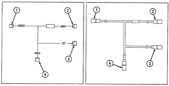
Connector No.
Electrical Lead To:
Wire No.
1
Generator cutout switch
450A
2
Bilge pump switch
450
3
Auxiliary outlet
37
4
Circuit breaker no. 3
450
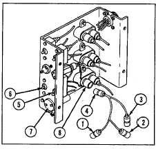
a. REMOVAL
1 Disconnect connector (1) from generator cutout
switch (5).
2 Disconnect connector (2) from bilge pump switch
(6).
3 Disconnect connector (3) from auxiliary outlet (7).
4 Disconnect connector (4) from circuit breaker no. 3
(8).
b. DISASSEMBLY
Disassemble lead assembly (see Chapter 6, Section VII).
c. ASSEMBLY
Assemble lead assembly (see Chapter 6, Section VII).
6-225