SECTION II: TRANSMISSION OIL COOLER LINES, BRACKET, SADDLE
TM 9-2350-256-20
SEALS, AND OUTPUT REDUCTION DRIVES
7-8 REPLACE TRANSMISSION SADDLE SEALS
THIS TASK COVERS
a. Removal
b. Installation
INITIAL SET-UP
Tools:
Parts:
Equipment Condition:
Tool kit, general mechanic's
Packings, preformed (4)
Powerplant removed (see
(Appendix C, item 53)
(Appendix G, item 186)
paragraph 3-1)
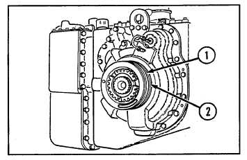
NOTE
Removal and installation procedures are the same for both left- and right-side transmission saddle seals.
a. REMOVAL
Pry out and remove two performed packings (1) from each
side of transmission saddle (2).
b. INSTALLATION
Install two new preformed packings (1) on each side of
transmission saddle (2).
NOTE
Follow-on maintenance:
Install powerplant (see
paragraph 3-1)
7-9 REPLACE TRANSMISSION OUTPUT REDUCTION DRIVES AND DRIVE COUPLINGS
THIS TASK COVERS
a. Removal
b. Installation
INITIAL SET-UP
Tools:
Parts:
• Tool kit, general mechanic's (Appendix C,
• Bolts, self-locking (38) (Appendix G, item 3)
item 53)
• Pins, cotter (2) (Appendix G, item 212)
• Bolts, machine (jackscrews) (2) (Appendix C,
item 2)
Equipment Conditions:
• Multiplier, torque (Appendix C, item 27)
• Powerplant removed (see paragraph 3-1)
• Sling assembly, lifting (Appendix C, item 46)
• Final drive hub and sprockets removed (see
• Socket set (Appendix C, item 48)
paragraph 8-10)
• Wrench, torque (Appendix C, item 25)
NOTE
Removal procedure is the same for both left- and right-side output reduction drives.
7-11