SECTION II: TRANSMISSION OIL COOLER LINES, BRACKET, SADDLE
TM 9-2350-256-20
SEALS, AND OUTPUT REDUCTION DRIVES
8
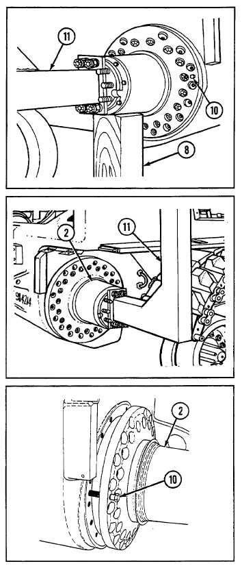
Install lifting sling (11).
9
Remove two jackscrews (10).
10 Remove wooden block (8).
WARNING
Output reduction drive (2) must clear hull
when assembly is lifted by lifting sling (11).
If assembly does not clear hull during lift,
weight of vehicle will be transferred to lifting
sling causing lifting sling failure. All
personnel are to stand clear of vehicle hull
when lifting operation starts.
11 Remove output reduction drive (2) using lifting
sling (11).
b. INSTALLATION
1
Install lifting sling (11) on output reduction drive (2).
NOTE
Do not thread jackscrews (10) all the way
through output reduction drive (2) at this time.
2
Install two jackscrews (10).
WARNING
Output reduction drive (2) must clear hull
when assembly is lifted by lifting sling (11).
If assembly does not clear hull during lift,
weight of vehicle will be transferred to lifting
sling causing lifting sling failure. All
personnel are to stand clear of vehicle hull
when lifting operation starts.
3
Install output reduction drive (2) using lifting sling (11).
4
Place wooden block (8) under output reduction drive
(2).
5
Thread two jackscrews (10) into hull and remove lifting
sling (11).
6
Tighten two jackscrews (10) alternately to draw output
reduction drive (2) against mating surface.
7-13