TM 9-2350-256-20
CHAPTER 8: MAINTENANCE OF SUSPENSION SYSTEM
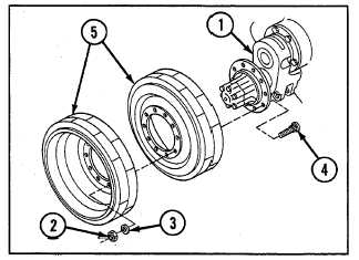
8-8 REPLACE COMPENSATING IDLER ARM ASSEMBLY WHEELS, HUB ASSEMBLY, LINKS, AND LINK
BEARINGS--Continued
9 Install two compensating idler wheels (5), ten bolts
(4), ten washers (3), and ten new self-locking nuts
(2). Torque self-locking nuts to 320-350 lb-ft (434-
475 N m).
10 Remove blocking and lower idler arm assembly
(1).
NOTE
Follow-on maintenance: Tighten track tension (refer
to TM 9-2350-256-10)
8-9 PLACE/SERVICE COMPENSATING IDLER AND ARM ASSEMBLY
THIS TASK COVERS
a. Removal
b. Cleaning
c. Inspection
d. Installation
INITIAL SET-UP
Tools:
Materials/Parts-Continued:
Tool kit, general mechanic's (Appendix C,
Seal assemblies (2) (Appendix G, item 263)
item 53)
Seals (2) (Appendix G, item 273)
Handle (Appendix C, item 18)
Washers, key (2) (Appendix G, item 277)
Replacer (Appendix C, item 40)
Wrench (Appendix C, item 60)
Equipment Conditions:
Roadwheel removed (see paragraph 8-1)
Materials/Parts:
Compensating idler wheel and hub assembly
Grease (Appendix D, item 13)
removed and link disconnected (see paragraph
Oil, OE (Appendix D, item 18)
8-8)
Solvent, dry-cleaning (Appendix D, item 9)
Track disconnected (refer to TM 9-2350-256-10)
Gaskets (2) (Appendix G, item 47)
WARNING
Ensure track is blocked when performing suspension maintenance. If track is not blocked,
vehicle may roll and may cause severe injury or death to personnel.
Compensating idler arm is heavy and may cause injury if dropped.
NOTE
Left and right sides are removed and installed in the same manner.
a. REMOVAL
1 Remove six screws (1) and compensating idler arm (2) from vehicle hull.
8-28