TM 9-2350-256-34
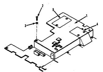
Figure 2-50. Right-side front floor plate--removal and
installation
2-47. Right-Side Front Floor Plate
NOTE
Refer to figure to locate cab subfloor plates.
a.
Removal. Prior to removing the right-side -j front
floor plate, remove hydraulic control panel (subplate)
assembly as shown in figure 2-28, and right-front access
floor plate, right-front floor plate rear access, APU control
box and shifting controls and linkage as shown in TM 9-
2350-256-20.
Remove right-side front floor plate as shown in figure 2-
50.
b.
Installation. Install the right-side front floor plate
in reverse order of removal.
1
Right-side front floor plate
2
Screw (7)
3
Lockwasher (7)
4
Right-front floor plate rear access
5
Right-front &access floor plate
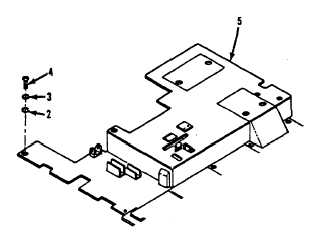
Figure 2-51. Left side front floor plate removal and
installation
2-48. Left-Side Front Floor Plate
NOTE
Refer to figure 2-3 to locate cab subfloor plates.
a.
Removal. Prior to removing the left-side front
floor plate disconnect wiring harness from dimmer switch
and remove right-side front floor plate (figure 2-50).
Remove left-side front floor plate as shown in figure 2-5L
b.
Installation. Install the left-side front floor plate in
reverse order of removal.
1
Left-side front floor plate
2
Flat washer (2)
3
Lockwasher (2)
4
Screw (2)
5
Right-side front floor plate
2-84 (2-85 and 2-86 Deleted) CHANGE 7