TM 9-2350-256-34-2
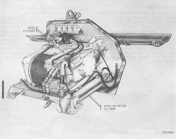
Figure 1-5. Main winch and spade assembly— right rear view.
(b) Main winch (fig. 1-4). The main winch is installed in the forward part of the vehicle hull beneath the
crew compartment. It is used for heavy-duty winching operations, and has a capacity of 90, 000 pounds using
a single line.
(c) Spade (fig. 1-4). The spade is hydraulically controlled and is externally mounted on the front of the
vehicle. It is primarily used to stabilize the vehicle when loads above 12, 000 pounds are winched or hoisted.
(d) Spade-actuating cylinders (fig. 1-5). The spade is hydraulically actuated by means of two, single-end
rod, double-acting spade cylinders. These cylinders are located in the hull of the vehicle beneath the crew
compartment; one on each side of the main winch.
(e) Main winch combination control valve (fig. 1-4). The main winch combination control valve is mounted
on top of the hydraulic motor manifold. It is a three-position, center-open valve, and serves to direct hydraulic
flow through the -6 Change 1 manifold to the hydraulic motor, thus determining the direction of motor rotation.
(f) Cable level winder assembly (fig. 1-4). The cable level winder assembly is mounted on the inside of
the vehicle hull, directly beneath the main winch cable guide plate. The assembly is synchronized with main
winch operation and ensures even winding and unwinding of the main winch cable.
(g) Main winch hydraulic motor (fig. 1-5). The hydraulic motor is mounted at the rear of the main winch
on the underside of the manifold. It is a vane-type, reversible motor which serves to convert hydraulic energy
into rotary motion and torque. This torque is then transmitted to the main winch. (See paragraph (e) above).
(h) Main winch brake cylinder (fig. 1-5). The main winch brake cylinder is located on the brake housing at
the rear of the main winch. Within the cylinder is a piston which is spring-loaded to the applied position. The
piston exerts force on the brake drum to prevent cable drum movement in
1-6 Change 1