
TM 9-2350-256-34
0053 00
2.
Place load on winch. Use calibrated weights or load cell if available. Load cell must be anchored.
If a load cell or weights are unavailable, attach cable to an anchor or adjust winch brake full tight. Refer to WP
3.
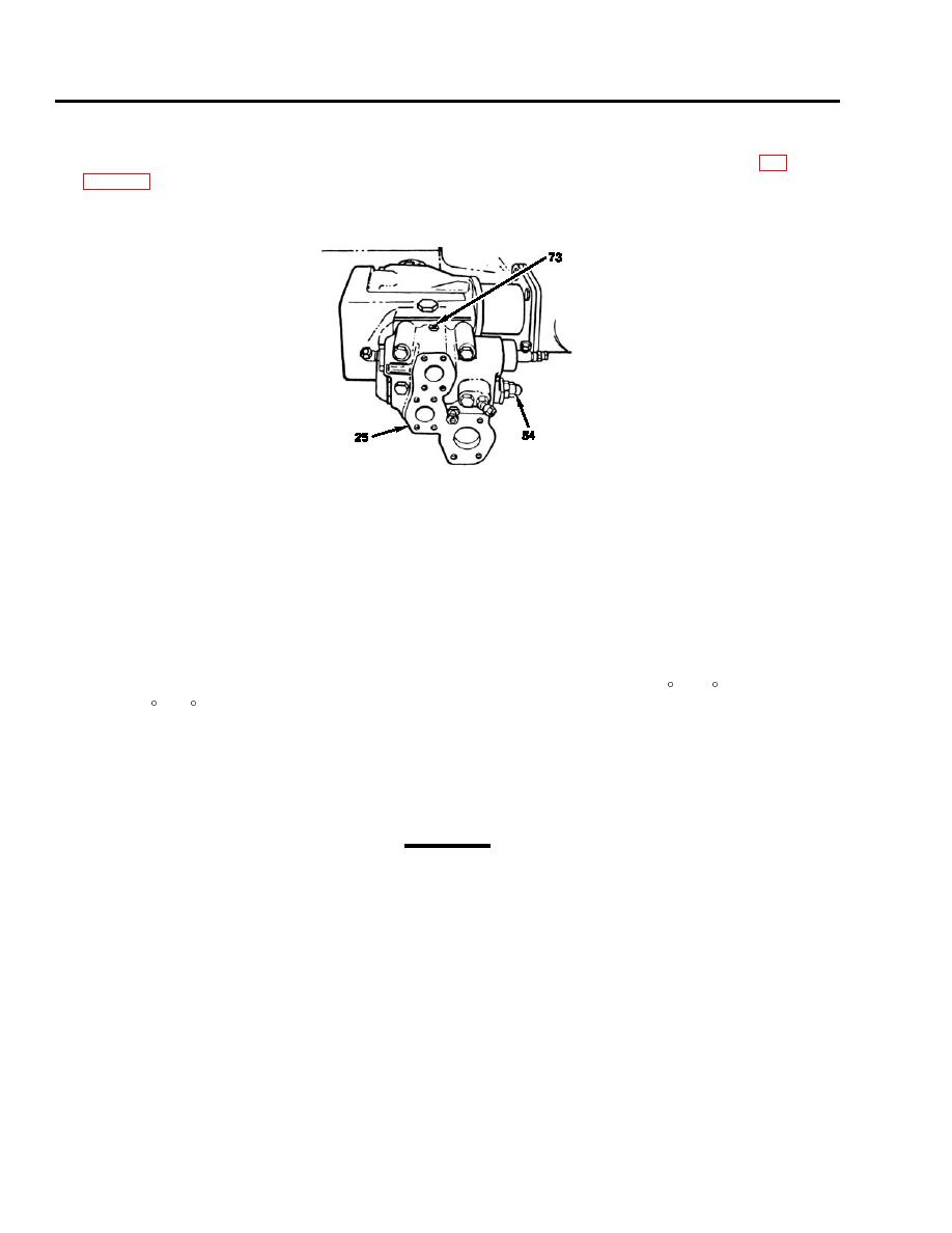
If using anchor or winch brake, use adjusting screw (54) on hoist winch combination control valve (25) to reduce pressure
as far as possible. Turning in counterclockwise direction will decrease pressure.
4.
Set engine speed at 16001800 rpm.
NOTE
HOIST WINCH COMBINATION CONTROL VALVE ADJUSTMENT--Perform steps 5 thru 10 to
adjust the hoist winch combination control valve to achieve hoisting requirements.
NOTE
This adjustment must be performed with the hydraulic reservoir oil temperature at 100 F130 F
(38 C54 C).
5.
If using calibrated weights or load cell, use adjusting screw (54) on hoist winch combination control valve (25) to achieve
maximum lift of 50,00055,000 lb (22,68024,948 kg). Turning in clockwise direction will increase pressure.
6.
Activate winch to raise in low gear.
CAUTION
Do not exceed 1000 psi (6895 kPa) relief pressure.
7.
If using anchor or winch brake, adjust relief pressure to original value recorded in Vehicle Log Book.
8.
Verify setting with locking nut in locked position, and record new setting in Vehicle Log Book.
9.
Disconnect pressure gage. Disconnect weights, load cell, or anchor, or readjust winch brake as necessary.
NOTE
If smooth lowering capability is not obtained, adjust counterbalance valve (60). Refer to step 4 under
TESTING below for adjustment procedure.
0053 00-14

