
TM 9-2350-256-34
0069 00
2.
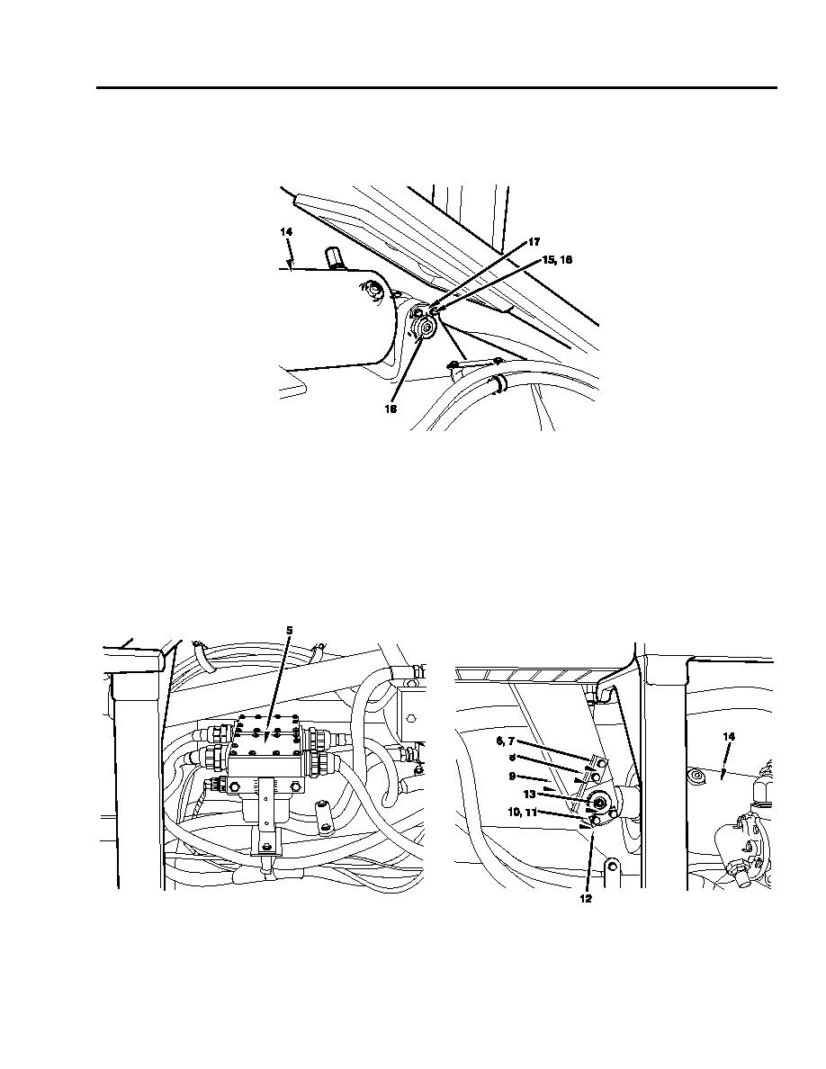
Tie or block cylinder (14) to position.
3.
Align holes with tapered drift and install cylinder eye pin (18) to cylinder (14) using wood block and hammer to tap pin in
place.
4.
Install retainer (17), two lockwashers (16), and screws (15) holding cylinder eye pin (18) to cylinder (14).
5.
Align holes with tapered drift and install piston eye pin (13) to crank arm (9) and cylinder (14) using wood block and
hammer to tap pin in place.
6.
Install retainer (12), two lockwashers (11), and screws (10) holding piston eye pin (13) to crank arm (9) and cylinder (14).
7.
Install limit valve cam follower bracket (8), two lockwashers (7), and screws (6) to crank arm (9).
NOTE
Step 8 is for clearance for piston eye pin operation, right cylinder.
8.
Install master and armature relays and bracket (5) in accordance with TM 9-2350-256-20.
0069 00-5

