TM 9--2350--292--20--1
FUEL/WATER SEPARATOR AUTOMATIC DRAIN SYSTEM AND WIRING
HARNESS E2CA128--006 REPLACEMENT -- CONTINUED
0219 00
Installation--Continued
CAUTION
Be sure to install probes in proper separator ports. Probe
with lead attached to side of control module is installed in
upper port. Failure to comply may result in damage.
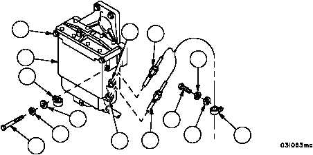
16. Connect upper and lower water sensor probes with leads (6) to two adapters (7).
17. Secure upper water sensor probe (6) with screw (10), new lockwasher (11), flat washer (12) and clamp (13).
18. Secure lower water sensor probe (6) with screw (1), new lockwasher (2), flatwasher (3) and clamp (4). Tighten
three remaining screws (1).
Figure 29
1
7
6
7
6
5
1
2
4
3
11
12
10
13
NOTE
FOLLOW--ON MAINTENANCE:
Bleed fuel/water separator (WP 0220 00)
Install powerpack (WP 0188 00)
END OF TASK
0219 00--5/6 blank