TM 9--2350--292--20--1
0226 00--16
ACCELERATOR CONTROLS AND LINKAGE REPAIR -- CONTINUED
0226 00
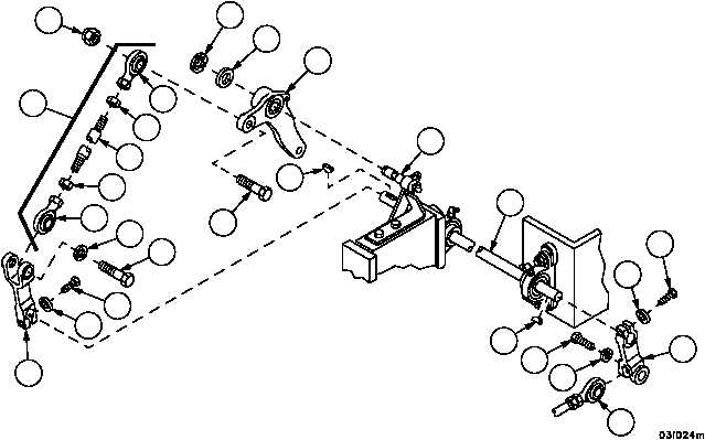
Installation--Continued
47. Install lever (33) with woodruff key (36) on shaft (29).
48. Install screw (34) and new lockwasher (35) in lever (33).
49. Install screw (30) and new lockwasher (31) securing rod assembly (32) to lever (33).
50. Install clevis (17) on shaft (29) with woodruff key (28).
51. Install screw (26) and new lockwasher (27) in clevis (17).
52. Install bell crank (7) on bracket assembly (23).
53. Install flat washer (25) and new retaining ring (24) on bracket assembly (23).
54. Install two nuts (20) and two rod ends (18 and 19) on rod (21).
55. Install rod assembly (14) to clevis (17) using screw (15) and new lockwasher (16).
56. Attach rod assembly (14) to bell crank (7) with screw (13) and new self--locking nut (12).
Figure 35
33
34
35
31
30
36
28
29
23
32
12
18
20
21
20
19
16
15
13
17
27
26
14
24
25
7