TM 9--2350--292--20--1
ACCELERATOR CONTROLS AND LINKAGE REPAIR -- CONTINUED
0226 00
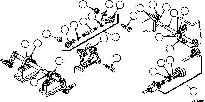
Installation--Continued
57. Install two nuts (10) and two rod ends (8 and 9) on rod (11).
58. Attach rod assembly (3) to bell crank (7) with screw (6) and new self locking nut (5).
59. Attach rod assembly (3) to engine throttle lever (4) with screw (2) and new self--locking nut (1).
60. Move the shaft (29) left or right until the linkage on both sides is perpendicular to the shaft (29) and will operate
without binding.
61. Hold shaft (29) in position and tighten setscrews (42) on pillow blocks (41).
62. Lubricate four pillow blocks (41 and 112) through four lubrication fittings (43 and 119) (WP 0187 00).
63. Align and adjust accelerator and hand throttle controls (WP 0227 00).
64. Tighten clamp (60) securing boot (59) and bushing (61) on rod assembly (32).
Figure 35
1
4
8
2
10
10
11
9
5
3
7
6
29
32
43
41
43
42
41
59
60
61
42
112
119
119
112
NOTE
FOLLOW--ON MAINTENANCE:
Install vehicular tool box rack and oddment tray
assembly (WP 0480 00)
Install air cleaner intake hoses (WP 0212 00)
Install engine deck (WP 0417 00)
Install engine deck grilles (TM 9--2350--292--10)
Install subfloor plates #19 and #24 (WP 0454 00)
END OF TASK
0226 00--17/18 blank