TM 9--2350--292--20--1
0235 00--1
ENGINE COOLING FANS AND HOUSINGS REPLACEMENT
0235 00
THIS WORK PACKAGE COVERS:
Removal, Installation
INITIAL SETUP:
Tools and Special Tools
General mechanic’s tool kit (item 1, WP 0717 00)
Torque wrench (item 2, WP 0717 00)
Fan rotor gauge (item 114, WP 0717 00)
Materials/Parts
Lockwashers (6) (item 2, WP 0718 00)
Cotter pin (item 30, WP 0718 00)
Cotter pins (16) (item 15, WP 0718 00)
Materials/Parts -- Continued
Gasket (item 358, WP 0718 00)
Seal (item 359, WP 0718 00)
Assembled--washer screws (10) (item 419,
WP 0718 00)
Equipment Conditions
Engine deck assembly removed (WP 0417 00)
NOTE
There are two engine cooling fans and centrifugal hous-
ings on the engine. Both are replaced in the same man-
ner. One of the cooling fans’ centrifugal housings is
mounted to the radiator fan shroud, the other to the
mounting bracket. The radiator fan shroud and mounting
bracket are replaced in the same manner. This task re-
places one cooling fan, one centrifugal housing and the
radiator fan shroud.
Removal
NOTE
Three different length screws secure the centrifugal hous-
ing to the radiator fan shroud or mounting bracket. Mark
each screw during removal and note the location to aid in
proper placement during installation.
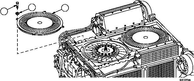
1. Remove four screws (1), four lockwashers (2) and centrifugal housing (3) from engine. Discard lockwashers.
Figure 42
1
2
3