TM 9--2350--292--20--1
0247 00--1
APU CONTROL BOX AND APU CONTROL BOX BRACKET REPAIR
0247 00
THIS WORK PACKAGE COVERS:
Removal, Disassembly, Assembly, Installation
INITIAL SETUP:
Tools and Special Tools
General mechanic’s tool kit (item 1, WP 0717 00)
Materials/Parts
Lockwashers (4) (item 85, WP 0718 00)
Lockwashers (6) (item 58, WP 0718 00) (old
configuration)
Lockwashers (4) (item 58, WP 0718 00) (new
configuration)
Lockwashers (12) (item 112, WP 0718 00)
Lockwashers (11) (item 90, WP 0718 00)
Lockwashers (5) (item 9, WP 0718 00)
Lockwasher (item 93, WP 0718 00)
Lockwashers (4) (item 390, WP 0718 00)
Marker tags (item 49, WP 0716 00 )
Materials/Parts--Continued
Gasket (item 92, WP 0718 00)
Gaskets (2) (item 91, WP 0718 00)
Equipment Conditions
Vehicle MASTER switch OFF (TM 9--2350--292--10)
Battery power disconnected (WP 0256 00)
Bleed valve manifold angle bracket and brace
removed, if installed (WP 0361 00 or WP 0362 00)
References
TM 9--2350--292--10
Removal
NOTE
Some vehicles may be equipped with a bleed valve manifold and gauge
which must be removed prior to performing this task.
Tag all electrical connections and electrical leads prior to removal to
aid in installation.
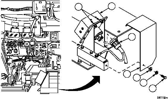
1. Remove screw (1), lockwasher (2), flat washer (3) and loosen two screws (4) at top of control box assembly (5).
Remove cover (6). Discard lockwasher.
2. Disconnect wiring harness 4W700 connector P1 (7) from APU control box assembly (5).
Figure 65
5
3
2
1
6
4
7