TM 9--2350--292--20--1
0248 00--3
PERSONNEL HEATER CONTROL BOX ASSEMBLY REPAIR -- CONTINUED
0248 00
Disassembly--Continued
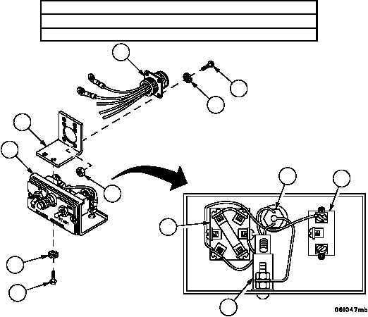
6. Remove two screws (20), two lockwashers (21), four nuts (22), four screws (23) and four lockwashers (24) from
wiring harness 4W146 (25). Discard lockwashers.
NOTE
Retain wire attaching hardware. Hardware is part of com-
ponent and required for installation.
Refer to electrical schematic (FP--5) for internal wiring of
personnel heater control box assembly.
7. Disconnect wiring harness 4W146 (25) from the following places, then remove wiring harness 4W146 (25) and
bracket (26) from heater control box lower half (9).
4W146 Wire
Disconnect From Component
401
Pin 12 of Heater Switch (27)
402
Pin 14 of Heater Control Switch (28)
403
Pin 20 of Heater Control Switch (28)
405
Pin 17 of Circuit Breaker (19)
407
Pin 19 of Heater Control Switch (28)
8. Disconnect indicator lamp assembly (29) from the following places:
4W191 Wire
Disconnect From Component
405
Pin 17 of Circuit Breaker (19)
407
Pin 19 of Heater Control Switch (28)
Figure 68
26
25
24
23
21
20
9
29
27
19
28
22