TM 9--2350--292--20--1
0022 00--1
BATT/GEN GAUGE READS IN YELLOW OR LOWER RED WITH APU
RUNNING AND APU GEN SWITCH ON.
0022 00
THIS WORK PACKAGE COVERS:
Batt/Gen Gauge Reads In Yellow Or Lower Red With Apu Running And Apu Gen Switch On
INITIAL SETUP:
Tools and Special Tools
General mechanic’s tool kit (item 1, WP 0717 00)
Multimeter (item 84, WP 0717 00)
Materials
Adhesive (item 25, WP 0716 00)
Equipment Conditions
APU shut down (TM 9--2350--292--10)
Vehicle MASTER switch OFF (TM 9--2350--292--10)
APU removed and APU ground hop kit installed
(WP 0589 00)
Personnel Required
Two
no
yes
Repair (WP 0290 00) or replace
(WP 0312 00) harness 3W710.
Verify fault is corrected.
Is 28 V dc present?
1. Turn MASTER switch ON (TM 9--2350--292--10).
2. Start APU (TM 9--2350--292--10).
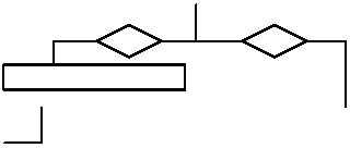
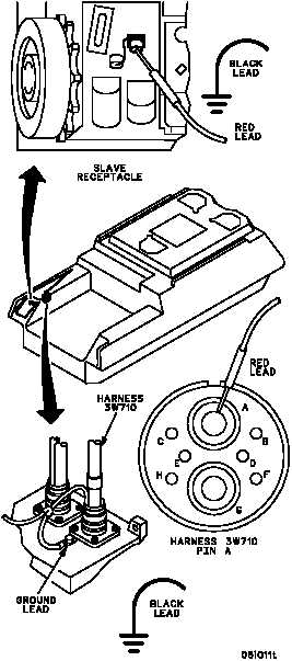
3. Place multimeter red lead on center conductor of
slave receptacle and black lead to ground.
Check for voltage.
4. Shut off APU (TM 9--2350--292--10).
5. Turn MASTER switch OFF.
no
yes
Is 28 V dc present?
Go to WP 0085 00.
A
1. Remove splash cover protecting voltage regulator
(WP 0239 00).
2. Disconnect harness 3W710 P1 from APU voltage
regulator, but do not remove ground lead.
3. Turn MASTER switch ON (TM 9--2350--292--10).
4. Start APU (TM 9--2350--292--10).
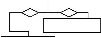
5. Place multimeter red lead on harness 3W710 pin
A and black lead to ground. Check for voltage.
6. Shut off APU (TM 9--2350--292--10).
7. Turn MASTER switch OFF.
B
CONTINUED ON NEXT PAGE
WARNING
Remove rings, bracelets, wristwatches,
and neck chains before working on any
vehicle. Jewelry can catch on equip-
ment and cause injury, or may short
across an electrical circuit and cause
severe burns or electrical shock.