TM 9--2350--292--20--1
0071 00--4
SIGNALS FROM SENSOR IS BELOW ITS VALID RANGE, INDICATES BOTH
CIRCUITS ARE OPEN, IS ABOVE ITS VALID RANGE, INDICATES CIRCUITS
ARE CLOSED, OR WAS NOT PROCESSED CORRECTLY -- CONTINUED
0071 00
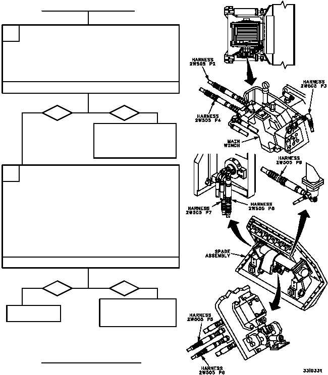
1. Reconnect wiring harness 4W504 connector
P1 to remote terminal unit connector J2.
2. Disconnect wiring harness 2W505 from sensor
that is failing (WP 0676 00).
3. Use table in step A to conduct a continuity
check of wiring harness 2W505 wires that
correspond to the sensor that is failing.
B
CONTINUED ON NEXT PAGE
CONTINUED FROM STEP NO TAG
Is continuity present?
yes
no
Repair (WP 0290 00) or
replace (WP 0676 00)
wiring harness 2W505.
Verify fault is corrected.
1. Replace sensor that is failing (WP 0685 00 for
sensor 2MT535, 2MT536, 2MT537, 2MT538,
2MT539, 2MT540, 2MT541 or 2MT546, WP
0686 00 for sensor 4MT542 or 4MT543, or WP
0687 00 for sensor 4MT545).
2. Reconnect wiring harness 4W504 to sensors
and wiring harness 2W505 (WP 0680 00).
3. Reconnect wiring harness 2W505 to sensor, if
removed (WP 0676 00).
4. Install main winch ground hop kit (WP 0498 00).
5. Start Enhanced Diagnostics program
(WP 0086 00) and run selftest.
C
Does failing sensor now pass selftest?
yes
no
Replace remote termi-
nal unit (WP 0675 00).
Verify fault is corrected.
Fault corrected.