TM 9--2350--292--20--1
0121 00--4
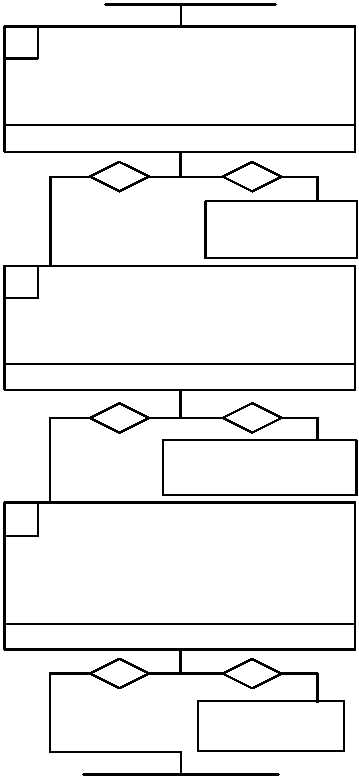
BLACKOUT DRIVE LIGHTS FAIL TO OPERATE -- CONTINUED
0121 00
CONTINUED FROM STEP F
CONTINUED ON NEXT PAGE
G 1. Place main light switch to BO DRIVE
(TM 9--2350--292--10).
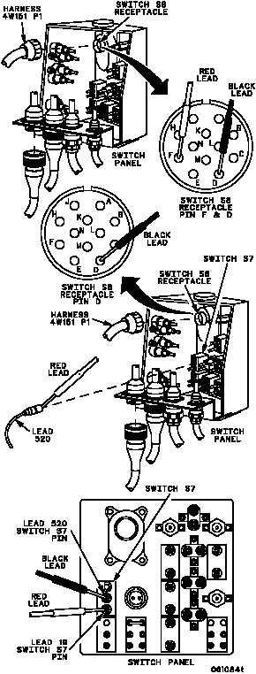
2. Place one multimeter lead on switch S8
receptacle pin F and other lead on switch S8
receptacle pin D. Check for continuity.
Is continuity present?
no
yes
Replace switch S8
(WP 0242 00). Verify
fault is corrected.
no
yes
H
I
1. Disconnect lead 520 from BO SELECTOR
switch.
2. Place one multimeter lead in harness S8
switch S8 receptacle pin D and other lead in
lead 520 connector socket. Check for
continuity.
Is continuity present?
Is continuity present?
no
yes
Replace switch S7
(WP 0242 00). Verify
fault is corrected.
1. Reconnect harness 4W151 P1 to switch S8.
2. Disconnect lead 19 from switch S7.
3. Place BO SELECTOR switch to BO
SELECTOR (TM 9--2350--292--10).
4. Place one multimeter lead on lead 19 switch S7
pin and other lead on lead 520 switch S7 pin.
Check for continuity.
Repair (WP 0290 00) or re-
place (WP 0242 00) lead 520.
Verify fault is corrected.