TM 9--2350--292--20--1
POWER TAKEOFF ELECTRICAL SYSTEM OVERVIEW AND DIAGRAMS
0143 00
THIS WORK PACKAGE COVERS:
Power Takeoff Electrical System Overview and Diagrams
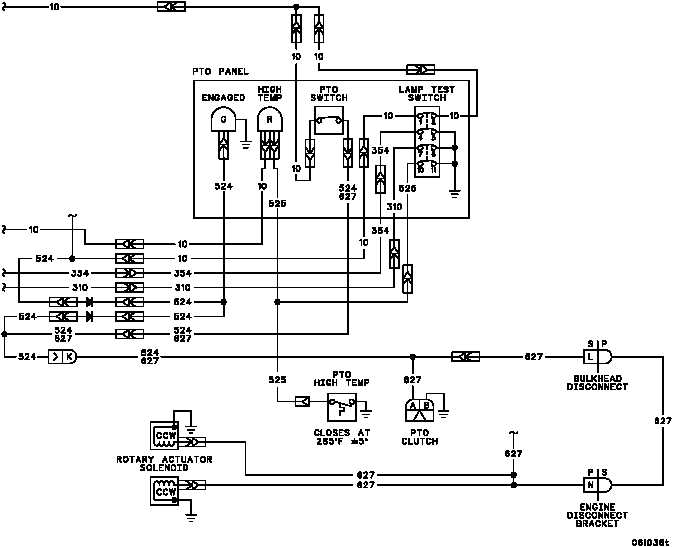
The power takeoff (PTO) electrical system consists of the PTO clutch, the ENGAGED indicator, PTO CLUTCH
switch, diode, 20--amp circuit breaker, engine governor solenoid, two rotary actuator solenoids, and related electri-
cal wiring.
With the main engine running and the MASTER switch set to ON, system power (+28 V dc) is supplied through a
20--amp circuit breaker on the hydraulic control panel to the PTO CLUTCH switch on the PTO clutch panel. Opera-
tion of the main hydraulic system is initiated by setting the PTO CLUTCH switch to the ON position. With the PTO
CLUTCH switch in the ON position, the PTO clutch is engaged, the ENGAGED indicator is lit, and engine power is
transmitted to the main hydraulic pumps. Additionally, both the main engine governor solenoid and the rotary ac-
tuator are energized. When the main engine governor solenoid is energized, the governor limits main engine veloc-
ity to 1800 rpm during main hydraulic system operations. When the rotary actuator solenoids are energized, air
flow is routed through the hydraulic oil cooler to reduce hydraulic fluid temperature.
The relationship of the various components of the PTO electrical system is shown in the following diagram.
END OF TASK
0143 00--1/2 blank