TM 9--2350--292--20--1
0165 00--2
WARNING SYSTEM OVERVIEW AND DIAGRAMS -- CONTINUED
0165 00
If the SYSTEM WARNING light comes on and the warning horn sounds when the main engine is running, normal
procedure is to shut down the main engine and identify and correct the malfunction. As an aid to operator and
maintenance personnel, the warning horn can be turned off by setting the HORN OVERRIDE switch in the open
(up) position after a malfunction has been detected. When the malfunction is identified and corrected, the HORN
OVERRIDE switch is returned to the closed position (down) for normal vehicle operation.
The lamp test electrical circuits consists of the LAMP TEST switch, PTO clutch oil high TEMP warning light, and
PTO clutch ENGAGED indicator light, all of which are located on the accessory control panel; the hydraulic LOW
OIL LEVEL indicator light, RETURN FILTER CLOGGED indicator light, CHARGE FILTER CLOGGED indicator
light, LOW BRAKE PRESSURE warning light, hydraulic MAX OIL TEMP EXCEEDED (225_ F) indicator light.
TRANS FILTER CLOGGED INDICATOR LIGHT, LEVEL WINDER MALFUNCTION warning light, WINCH DRUM
MALFUNCTION warning light, PAYOUT LIMIT warning light, 20--amp circuit breaker, and 15--amp circuit breaker,
all of which are located on the hydraulic control panel; eight diodes and related electrical wiring.
When the main engine is running and the LAMP TEST switch on the accessory control panel is held in the TEST
position, all warning lights on the hydraulic control panel and PTO clutch control pane will be illuminated. In addi-
tion, the SYSTEM WARNING light will light and the warning horn will sound. This check ensures both the SYS-
TEM WARNING light, as well as other warning and indicator lights, and warning horn are all operational. If one of
the lamps do not light or the warning horn does not sound, normal procedure is to replace respective faulty LEDs or
warning horn whichever is applicable.
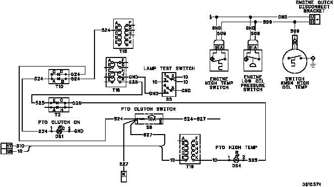
The relationship of the various warning system components is shown in the following diagram.