TM 9--2350--292--20--1
0176 00--1
SYSTEM WARNING INDICATOR WILL NOT COME ON WHEN ACTIVATING
WINCH TEST SWITCH.
0176 00
THIS WORK PACKAGE COVERS:
System Warning Indicator Will Not Come On When Activating Winch Test Switch.
INITIAL SETUP:
Tools and Special Tools
General mechanic’s tool kit (item 1, WP 0717 00)
Multimeter (item 84, WP 0717 00)
Equipment Conditions
Vehicle MASTER switch OFF (TM 9--2350--292--10)
Personnel Required
Two
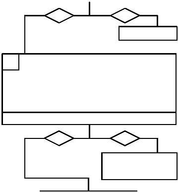
Is 24 V dc present?
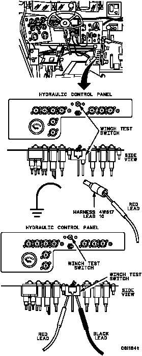
1. Disconnect harness 4W617 lead 10 from
winch test switch (WP 0330 00).
2. Turn vehicle MASTER switch ON
(TM 9--2350--292--10).
3. Place red multimeter lead in harness 4W617
lead 10 connector and black multimeter lead to
ground. Check for voltage.
4. Turn vehicle MASTER switch OFF
(TM 9--2350--292--10).
no
yes
no
yes
A
B
CONTINUED ON NEXT PAGE
1. Disconnect harness 4W617 lead 359 from
winch test switch (WP 0330 00).
2. Hold winch test switch in the ON position
(TM 9--2350--292--10) and place one
multimeter lead on each winch test switch
connector. Check for continuity.
3. Release winch test switch.
Is continuity present?
WARNING
Remove rings, bracelets, wristwatches,
and neck chains before working on any
vehicle. Jewelry can catch on equip-
ment and cause injury, or may short
across an electrical circuit and cause
severe burns or electrical shock.
Go to Step G.
Replace winch test
switch (WP 0245 00).
Verify fault is corrected.