TM 9--2350--292--20--2
0362 00--11
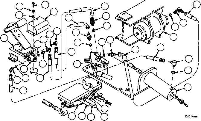
HYDRAULIC BRAKE HOSE ASSEMBLY, BLEED VALVE MANIFOLD AND
ASSOCIATED PARTS REPLACEMENT (NEW CONFIGURATION WITH BRAKE
MODULATION) -- CONTINUED
0362 00
Installation--Continued
19. Apply a thin coat of silicone compound to new preformed packings (30, 36 and 42).
20. Install one end of hose assembly (37), adapters (40 and 41) and new preformed packing (42) in port P of modulat-
ing valve (31).
21. Install other end of hose assembly (37) and adapter (38) and new preformed packing (39) in port POUT of power
boost manifold (11).
22. Install one end of hose (32), adapter (35) and new preformed packing (36) in port T of modulating valve (31).
23. Install other end of hose assembly (32), adapter (33) and new preformed packing (34) in port RIN of power boost
manifold (11).
24. Install one end of hose assembly (25), adapter (29) and new preformed packing (30) in port A of modulating valve
(31).
25. Install other end of hose assembly (25), adapter (26) and new preformed packing (27) in hydraulic cylinder (28).
26. Install two tiedown straps (43) around pillow blocks to support hose assemblies (25, 32 and 37) as illustrated in
figure.
27. Install five screws (20), five new lockwashers (21), five washers (22) and brake assembly cover (23) to brake as-
sembly (24).
28. Install one end of hose assembly (14), adapter (17) and new preformed packing (18) in accumulator (19).
29. Install other end of hose assembly (14), adapter (15) and new preformed packing (16) in port ACC of power boost
manifold (11).
43
32
37
43
25
20
21
23
31
24
32
33
34
11
37
38
39
17
18
19
14
26
27
28
25
14
15
16
22
25
30
29
3635
37
32
42
41
40