TM 9--2350--292--20--2
0389 00--2
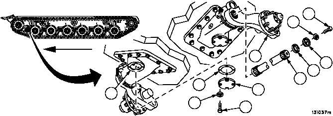
TORSION BARS AND TORSION BAR ANCHORS REPLACEMENT --
CONTINUED
0389 00
Removal
1. Remove screw (1), lockwasher (2), end plug (3) and spacer ring (4) from arm assembly (5). Discard lockwasher.
2. Install torsion bar adapter in end of torsion bar (6).
3. Install slide puller on torsion bar adapter.
WARNING
Arm assembly will fall free when torsion bar is removed.
Use extreme care to prevent injury.
4. Lift arm assembly (5) sufficiently to allow torsion bar (6) to be removed.
5. Pull torsion bar (6) through arm assembly (5) until torsion bar (6) splines clear arm assembly (5).
6. Remove slide puller and torsion bar adapter from torsion bar (6).
WARNING
Torsion bar weighs 110 lbs (49.94 kg). To avoid injury,
assistance is required to properly lift and safely remove
torsion bar from suspension arm.
Broken torsion bars have jagged and sharp edges. Ex-
treme caution should be taken to prevent injury during
removal.
7. Remove torsion bar (6) from arm assembly (5).
8. Remove four screws (7), four lockwashers (8), access cover (9) and gasket (10) from torsion bar housing (11).
Discard gasket and lockwashers.
Figure 17
1
2
3
4
5
6
7
8
9
10
11
ARMOR SKIRTS REMOVED FOR CLARITY
FORWARD