TM 9--2350--292--20--2
0394 00--2
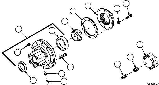
IDLER HUB ASSEMBLY REPAIR -- CONTINUED
0394 00
Disassembly
1. Remove eight screws (14), eight lockwashers (15), gasket (16) and seal assembly (17) from hub assembly (6).
Discard lockwashers and gasket.
2. Remove inner bearing (18) from idler arm assembly (10) spindle.
3. Remove relief valve (19) and bushing (20) from access cover (3).
NOTE
Bearing cones and bearing cups are used in matched
sets only. If either is damaged, cone and cup must be
replaced as a set.
4. Remove inner bearing cup (21) from hub assembly (6), if damaged.
5. Remove outer bearing cup (22) from hub assembly (6), if damaged.
NOTE
There are 10 screws in idler hub assembly. Remove only
those screws that are damaged.
6. Remove screws (23) from hub assembly (6).
7. Remove lubrication fitting (24) and bushing (25) from hub assembly (6).
8. Remove plug (26) from hub assembly (6).
Figure 186
3
20
19
6
23
21
18
26
25
24
22
15
17
16
14