TM 9--2350--292--20--2
0404 00--5
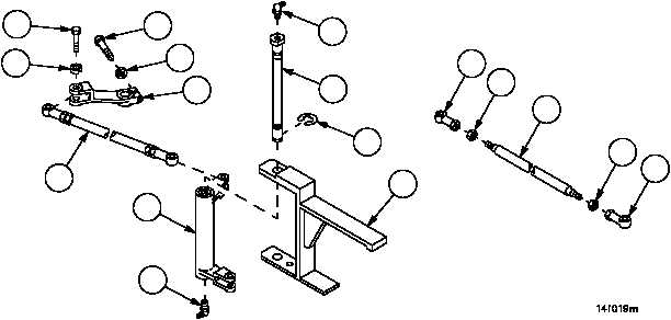
STEERING CONTROL LINKAGE (ENGINE COMPARTMENT) REPAIR --
CONTINUED
0404 00
Assembly
NOTE
All tubes, threaded rods, studs and connecting link
assemblies are assembled in the same manner.
Do not tighten nuts on tubes, threaded rods, studs, or
connecting link assemblies during assembly. Nuts will be
tightened during adjustment.
1. Install two nuts (48) on tube, threaded rod, stud or connecting link (49).
2. Install two bearings or clevises (50) on tube, threaded rod, stud or connecting link (49).
Installation
1. Install remote control lever (45) on transmission with screw (46) and new lockwasher (47).
2. Connect connecting link assembly (37) to remote control lever (45) with screw (43) and new lockwasher (44).
3. Install lubrication fitting (42) in pin (39).
4. Install bell crank (34) in mounting bracket (41) with pin (39).
WARNING
5. Install new retaining ring (40) on pin (39).
6. Install lubrication fitting (38) in pin (39).
Figure 194
43
44
46
47
45
37
34
38
41
40
39
42
50
48
49
50
48