TM 9--2350--292--20--2
0408 00--3
SHIFTING CONTROL LINKAGES ADJUSTMENT -- CONTINUED
0408 00
Adjustment--Continued
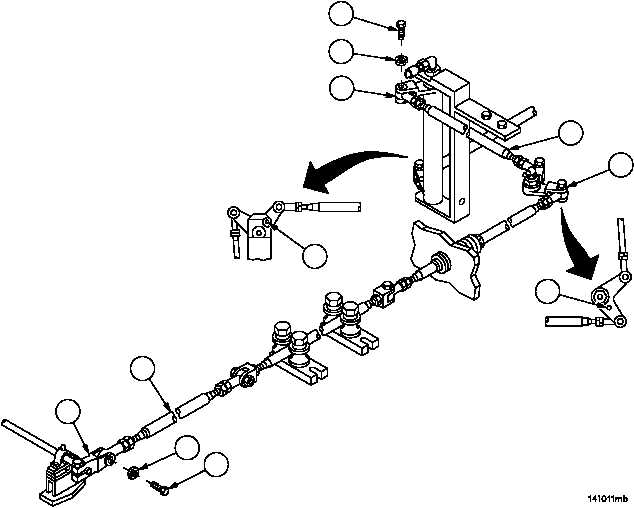
11. Insert welding electrode (21) in bell crank (22), adjust linkage between bell crank (22) and remote control lever
(17) until tube assembly (20) can be connected to remote control lever (17).
12. Connect tube assembly (20) to remote control lever (17) with screw (18) and new lockwasher (19).
13. Remove screw (23) and lockwasher (24), disconnect connecting link assembly (25) from bell crank (26). Discard
lockwasher.
14. Install welding electrode (27) in bell crank (26), adjust connecting link assembly (25) until connecting link assem-
bly (25) can be connected to bell crank (26).
15. Connect connecting link assembly (25) to bell crank (26) with screw (23) and new lockwasher (24).
Figure 193
23
24
26
27
25
22
21
17
20
19
18