TM 9--2350--292--20--2
0452 00--3
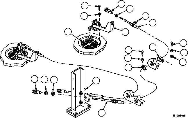
DRAIN VALVES, CONTROLS AND RELATED PARTS REPLACEMENT--
CONTINUED
0452 00
Removal--Continued
8. Remove three screws (25), three lockwashers (26) and bracket assembly (24) from drain valve assembly (27).
Discard lockwashers.
9. Loosen two cable nuts (28), remove bracket assembly (24) from control assembly (29).
10. Loosen clevis nut (30) at each end of control assembly (29).
11. Remove two cable clevises (3 and 20), two clevis nuts (30) and nut (31) from control assembly (29).
12. Remove control assembly (29) from cable spacer assembly (32).
NOTE
Front control assembly is secured to vehicle hull with one
clamp.
Rear control assembly is secured to vehicle hull with five
clamps.
Note location and quantity of attaching hardware to aid in
Installation
13. Remove screws (33), lockwashers (34), flat washers (35) and clamps (36). Discard lockwashers.
Figure 230
20
25
24
27
28
30
26
29
3
31
30
32
29
33
34
35
36
36
33
34
FRONT DRAIN VALVE
FRONT
BULKHEAD
REAR
BULKHEAD