TM 9--2350--292--20--2
0509 00--2
LEVEL WIND LIMIT SWITCHES ADJUSTMENT -- CONTINUED
0509 00
Adjustment--Continued
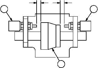
6. Measure and record air gap “X” between roller guide (3) and left limit switch (6).
7. Measure and record the air gap “Y” between roller guide (3) and right limit switch (8).
8. The sum of air gaps “X” and “Y” between roller guide (3) and left limit switch (6) and right limit switch (8) should be
between 0.78--0.94 inch (19.8--23.9 mm).
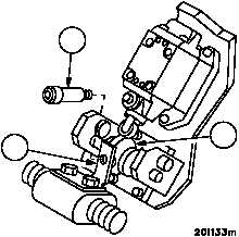
9. Apply sealing compound to threads of screw (1).
10. Install screw (1) to plate (2) and roller guide (3).
11. Torque screw (1) to 20--24 lb--ft (27--33 NSm)
Figure 269
X
Y
1
2
3
6
8
3
NOTE
FOLLOW--ON MAINTENANCE:
Install level winder guard (WP 0507 00)
END OF TASK