TM 9--2350--292--20--2
0355 00--3
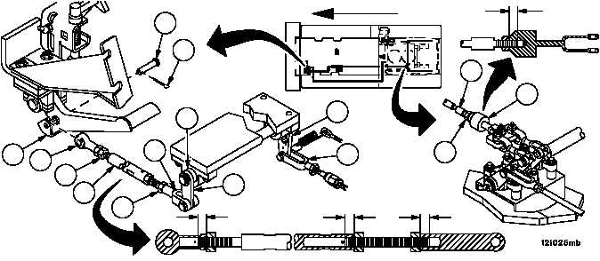
BRAKE LINKAGE ALIGNMENT, ADJUSTMENT AND BLEEDING
(OLD CONFIGURATION) -- CONTINUED
0355 00
Alignment -- Continued
WARNING
A minimum thread engagement of 0.50 inch (12.7 mm)
between brake cable assembly and clevis must be main-
tained at all times. Failure to comply could result in as-
semblies separation, causing loss of vehicle service
brake, resulting in personnel injury or vehicle damage.
9. Attach brake cable assembly (2) to clevis (3). Verify that a thread engagement of 0.50 inch (12.7 mm) between
threaded rod portion of brake cable assembly (2) and clevis (3) exist. Torque nut (1) to 15--20 lb--ft (20--27 NSm).
10. Remove cotter pin (14), pin (15) and rod assembly (16) from brake pedal (17). Discard cotter pin.
11. Disconnect rod assembly (18) from lever assembly (19) (WP 0366 00).
12. Restrain brake pedal (17) in UP position to steering wheel with rope.
WARNING
A minimum thread engagement of 0.62 inch (15.7 mm)
between rod assembly and clevis must be maintained at
all times. Failure to comply could result in assemblies
separation, causing loss of vehicle service brake, result-
ing in personnel injury or vehicle damage.
13. Loosen two nuts (20) and maximize the length of rod assembly (16) so that when rod assembly (16) is attached to lever
assembly (21), clevis (22) is within 0.12 inch (3 mm) of contacting brake shaft (23).
14. Verify thread engagement of 0.62 inch (15.7 mm) exists between ends of rod assembly (16) and clevises (22 and
24). Tighten two nuts (20).
15. Connect rod assembly (16) to brake pedal (17) with headed pin (15) and new cotter pin (14).
Figure 168
FORWARD
0.50 IN
(12.7 MM)
0.62 IN
(15.7 MM)
0.62 IN
(15.7 MM)
0.62 IN
(15.7 MM)
15
14
23
21
19
18
1
2
3
22
20
16
20
17
24