TM 9--2350--292--20--2
0355 00--8
BRAKE LINKAGE ALIGNMENT, ADJUSTMENT AND BLEEDING
(OLD CONFIGURATION) -- CONTINUED
0355 00
Bleeding
WARNING
1. Turn vehicle power switch to ON position to charge the brake system (TM 9--2350--292--10).
WARNING
Depressing brake pedal farther than necessary causes pressure in
brake cylinder to rise significantly. Brake pressure can rise to 900
psi (6201 kPa) if brake pedal is depressed too far. Use only as
much pedal travel as required to achieve steady fluid flow.
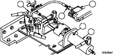
2. Depress brake pedal sufficiently to permit pressure to flow through brake cylinder (1).
3. Slowly loosen cylinder bleed screw (2) and allow fluid to flow until a steady stream of fluid is observed. This indi-
cates that all trapped air has been purged from cylinder (1).
4. Tighten cylinder bleed screw (2). Release brake pedal.
5. Turn vehicle MASTER switch to OFF (TM 9--2350--292--10). Exercise brake pedal while monitoring pressure
gauge (3) until the system pressure drops below 150 psi (1034 kPa).
6. Slowly loosen swivel fitting (4) at pressure switch (5) and allow fluid to flow until a steady stream of fluid is ob-
served. This indicates that all trapped air has been purged from lines.
7. Tighten swivel fitting (4).
8. Check hydraulic reservoir fluid level (TM 9--2350--292--10).
Figure 167
4
5
3
2
1
NOTE
FOLLOW--ON MAINTENANCE:
Close subfloor access plate #16, if opened (WP 0454 00)
Install hull engine compartment access covers, if removed
(WP 0434 00)
Install subfloor access plate #6, if removed (WP 0454 00)
Install powerpack, if removed (WP 0188 00)
END OF TASK