TM 9--2350--292--20--2
0556 00--2
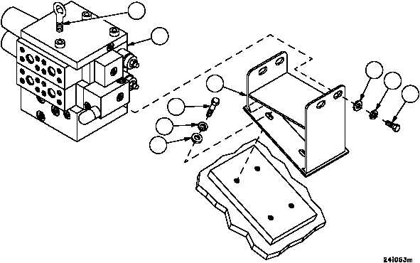
MAIN/HOIST WINCH DIRECTIONAL CONTROL VALVE ASSEMBLY
REPLACEMENT -- CONTINUED
0556 00
Installation
1. Install bracket (6) on hull with four screws (7), four new lockwashers (8) and four flat washers (9).
2. Attach lifting sling to lifting eye (4) and suitable lifting device.
3. Install directional control valve assembly (5) on bracket (6) with four screws (1), four new lockwashers (2) and four
flat washers (3).
Figure 302
3
2
1
5
6
7
8
9
4
NOTE
FOLLOW--ON MAINTENANCE:
Install hydraulic hoses and fittings on control valve as-
sembly (WP 0577 00)
Install main winch power reduction manifold and brack-
ets (WP 0557 00), if removed
Start engine, operate main winch and hoist winch hy-
draulic controls several times to purge air from hoses
and valve assembly (TM 9--2350--292--10)
Check hydraulic system for leaks, fill reservoir
(TM 9--2350--292--10)
Install subfloor plates support (WP 0454 00)
Install commander’s cupola (WP 0444 00)
END OF TASK