TM 9--2350--292--20--2
0357 00--5
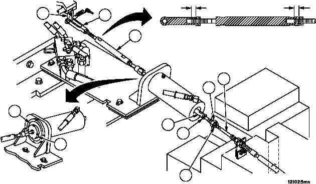
BRAKE LINKAGE ALIGNMENT, ADJUSTMENT AND BLEEDING
(NEW CONFIGURATION WITH BRAKE MODULATION) -- CONTINUED
0357 00
Alignment -- Continued
25. Disconnect rod assembly (19) from lever assembly (20) (WP 0367 00).
26. Loosen two nuts (35 and 36) and remove ball joint (37) from rod assembly (38) and brake cable assembly (2).
27. Ensure that disc (26) is resting against the face of brake cylinder (27).
28. Adjust rod assembly (19) until holes in lever assembly (20) and clevis (28) are aligned.
WARNING
A minimum thread engagement of 0.50 inch (12.7 mm)
between clevis and ball joint must be maintained at all
times. Failure to comply could result in assemblies sepa-
ration, causing loss of vehicle service brake, resulting in
personnel injury or vehicle damage.
29. Connect rod assembly (19) to lever assembly (20) (WP 0367 00).
0.50 IN
(12.7 MM)
0.50 IN
(12.7 MM)
20
28
19
2
37
38
35
36
26
27