
TM 9-2350-256-20-1
0056 00
CORRECTIVE ACTION Continued
7.
Reconnect bulkhead to APU to master relay and rigger's lights wiring harness to APU regulator.
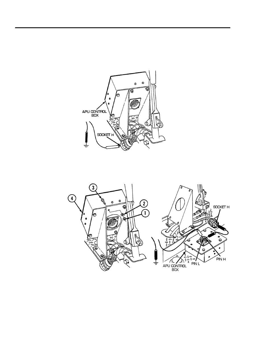
Disconnect APU control box to foot dimmer switch and bulkhead wiring harness from APU control
box. Place red lead of multimeter in socket H of wire 61 and black lead to ground. Turn MASTER
and APU GEN switches ON and check for voltage. Turn MASTER and APU GEN switches OFF. If
voltage is present, go to step 8. If voltage is not present, go to step 13.
8.
Remove four nuts (1), four lockwashers (2), four screws (3), and release APU control box (4) from
mounting brackets. Place a jumper from pin H to socket H. Place red lead of multimeter on pin L of
wire 61A and black lead to ground. urn MASTER and APU GEN switches on and check for voltage.
Turn MASTER and APU GEN switches OFF. If voltage is present, go to step 11. If voltage is not
present, go to step 9.
0056 00-6
