TM 9-2350-256-34-2
3-13. Repair of Hydraulic Subplate As-
sembly Components
a.
General. Remove and replace defective component
following sequence indicated in figure 3-20.
b.
Cleaning. Wash parts, except seals and gaskets, in
drycleaning solvent or mineral spirits paint thinner. Blow
parts with moisture-free compressed air; then immerse
parts in clean OE-10 oil, to prevent rusting.
c.
Inspection and Repair.
(1) Inspect all screws, plugs, nuts and fittings for
damaged threads and hex or socket heads for rounded
corners.
(2) Inspect all tapped holes for damaged
threads. Repair damaged threads with thread
chaser.
(3) Inspect valve bodies for cracks.
3-14. Assembly of Hydraulic Subplate
Assembly from Subassemblies
Assemble the hydraulic subplate assembly in reverse order
of disassembly (fig. 3-20)
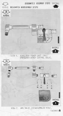
Figure 3-20. Disassembly of hydraulic subplate assembly
into subassemblies (Sheet 5 of 5).
Section IV. REPAIR OF MECHANICAL TRANSMISSION AND MAIN HYDRAULIC PUMP
ASSEMBLY
3-15. Description
The mechanical transmission and main hydraulic pump assembly (figs. 1-10 and 1011) is mounted in the hull beneath
the crew compartment. A power takeoff from the main engine drives the transmission which is coupled to the hydraulic
pump. The power hydraulic takeoff is engaged or disengaged by an internal transmission clutch,
3-16.
Disassembly of Mechanical Transmission and Main Hydraulic Pump Assembly into Subassemblies
a. General. Figure 3-21, with its accompanying legend, serves to identify all subassemblies and attaching parts. The
legend also provides an index to the step-by-step removal of each particular subassembly.
b. Disassembly Procedure. Disassemble the mechanical transmission and main hydraulic pump assembly into
subassemblies as shown in figures 3-21 and 3-22
Change1
3-31


