TM 9-2350-256-34
0082 00
Installation
NOTE
This procedure covers the right-hand valve. The left-hand valve is installed in the same manner except
there are only two hydraulic lines to be connected in step 8 for the left-hand valve.
1.
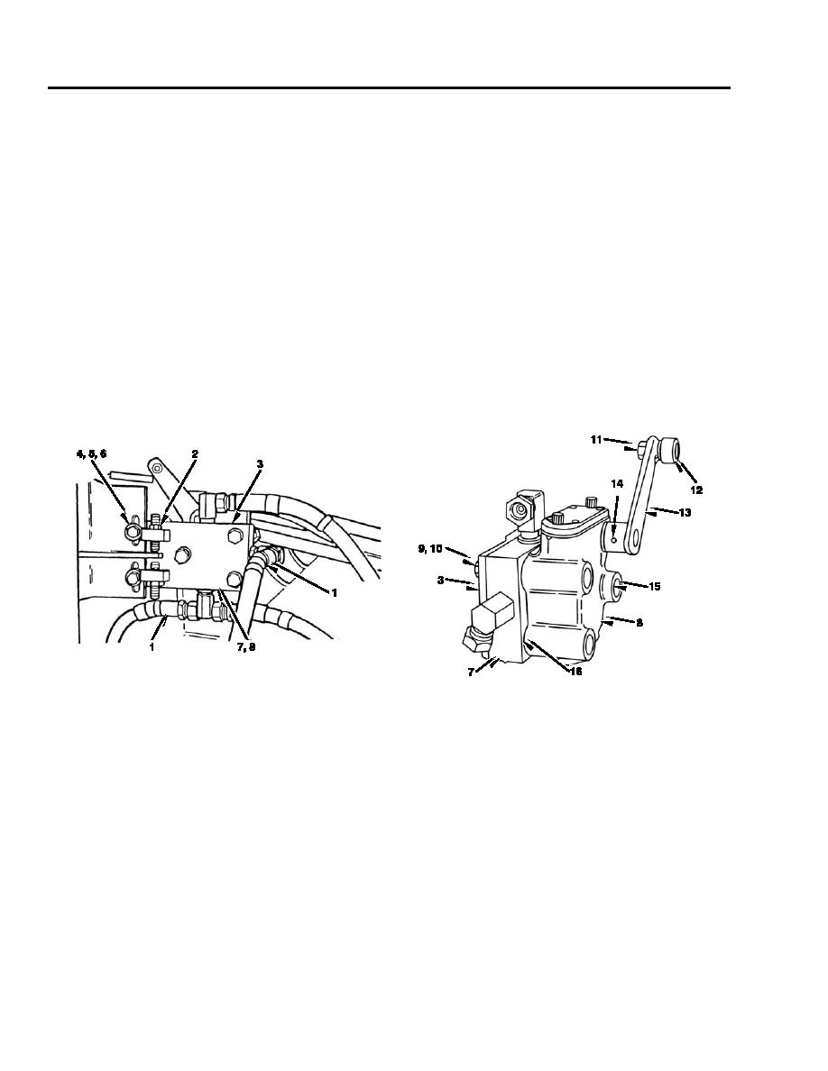
Install three packings (hidden) (16).
2.
Install valve (8) and three socket head screws (15) to subplate (7).
3.
Install arm (13) and spring pin (14) to valve (8).
4.
Install cam follower (12) and nut (11) to arm (13).
5.
Install support (3), three lockwashers (10), and screws (9) to subplate (7).
6.
Install support (3), subplate (hidden) (7), and valve (hidden) (8) together as an assembly, two washers (6), lockwashers (5),
and screws (4).
7.
Tighten two jamnuts (2) on support (3).
8.
Connect four hydraulic lines (1).
Adjustment
1.
Adjust boom limit pilot valve in accordance with TM 9-2350-256-20.
END OF WORK PACKAGE
0082 00-2


