TM 9--2350--292--20--2
0685 00--3
MAIN WINCH AND SPADE ASSEMBLY TRANSDUCERS AND RELATED
PARTS REPLACEMENT -- CONTINUED
0685 00
Removal--Continued
NOTE
All hydraulic lines and components must be tagged be-
fore removal for identification during installation.
Place rags under hydraulic connections to catch any hy-
draulic fluid that spills during maintenance. Dispose of
fluid soaked rags in accordance with standard operating
procedure.
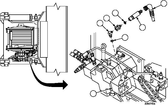
1. Remove wiring harness 2W505 connector P3 (1) from transducer 2MT536 (2).
2. Remove transducer 2MT536 (2) with straight swivel adapter (3) from elbow (4) then remove straight swivel adapt-
er (3) from transducer 2MT536 (2).
3. Remove elbow (4) from main winch motor relief valve (5).
4. Remove preformed packings (6 and 7) from straight swivel adapter (3) and elbow (4). Discard preformed packings.
1
2
3
4
5
6
7
NOTE:
MAIN WINCH HOSES
AND FITTINGS
REMOVED FOR CLARITY